
Here you see the starting point, a pump, seals kit with the control lever seal and driveshaft seal.A good lubrication of parts that push, contact, or slide is essential during the reassembly.Try to avoid disturbing the adjuster screws on the outside of the pump, otherwise you will need to take it to an injection specialist who has high-pressure gauges and precision flow measurement equipment to properly calibrate the pump. These adjustments are customized for your vehicle and engine and normally never need to be changed if doing a maintenance rebuild or replacing seals.

Here it is about an hour later. I did not take pictures of the disassembly, go in reverse from what follows if you have doubts for disassembly. Important settings to record:
- Full load adjusting screw • See here.
- Speed control lever graduations • See here.
- Governor shaft adjustment screw • See here.
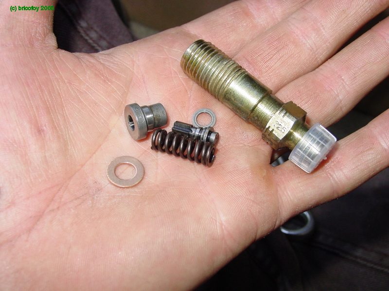
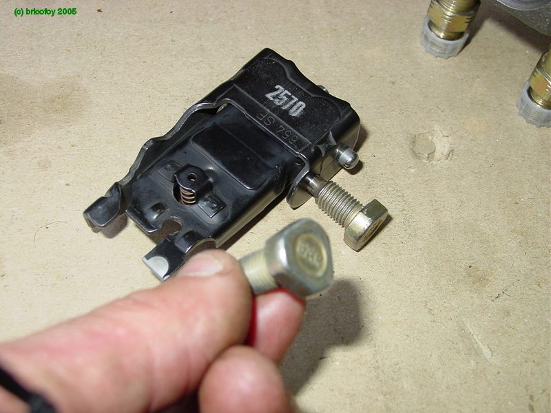
Get started by doing the distributor head hydraulics, it will always be so de facto. Below are the different components of the delivery valve holder. bushing, spring, shim, needle, and new sealing washer.
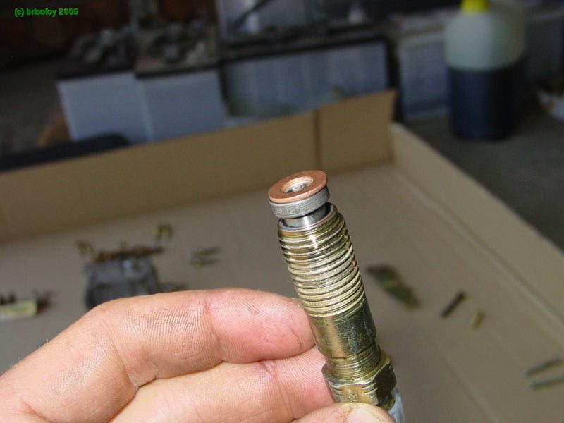
The copper sealing washer on the delivery valve holder.
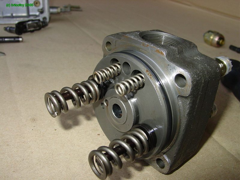
Removal of the distributor head should be done with the pump held with the fuel outlet stubs upward, with the fuel lines removed. The head should be pulled slowly and straight upwards to prevent parts from falling out of the pump.There is a long, tight-fitting shaft, the distributor plunger, which is the piston of the high pressure pump. This plunger needs to be removed carefully. Some springs will fall out of place but it is not important.When removing this plunger shaft its position relative to the drive shaft should be marked since it can be reassambled in two positions, depending on the cam-plate. There is a pin in the cam plate (skip to step #53) that forces the plunger to be properly aligned on the cam-plate, but the cam-plate can be assembled either of two ways. One way is 180 degrees off and will result in the pump injecting at the top of the exhaust stroke, not on the compression stroke. This camplate with its alignment dogs is shown in step #52 along with further warnings.You will re-install this plunger starting in step #57 where several photos are shown.

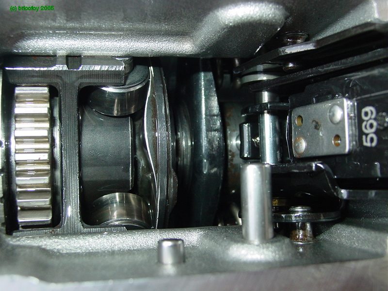
Woohoo, its competely disassembled! We see even my jeans clear through the bore.
Starting with the fuel feed pump, insert the stator ring.

Align 180° holes with the the pump housing taps (circled).
Then the rotor and vanes.
First, the rotor.
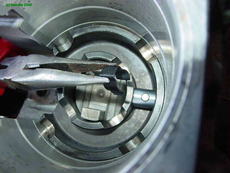
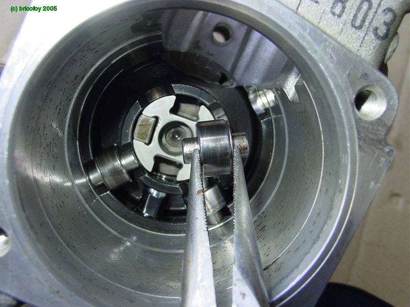
then the vanes using a needlenose plier.

then the pressure plate.

and tightened down.
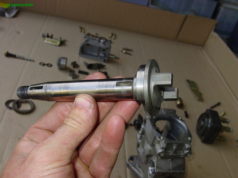
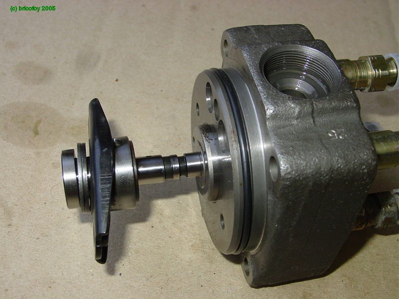
Assemble the driveshaft.
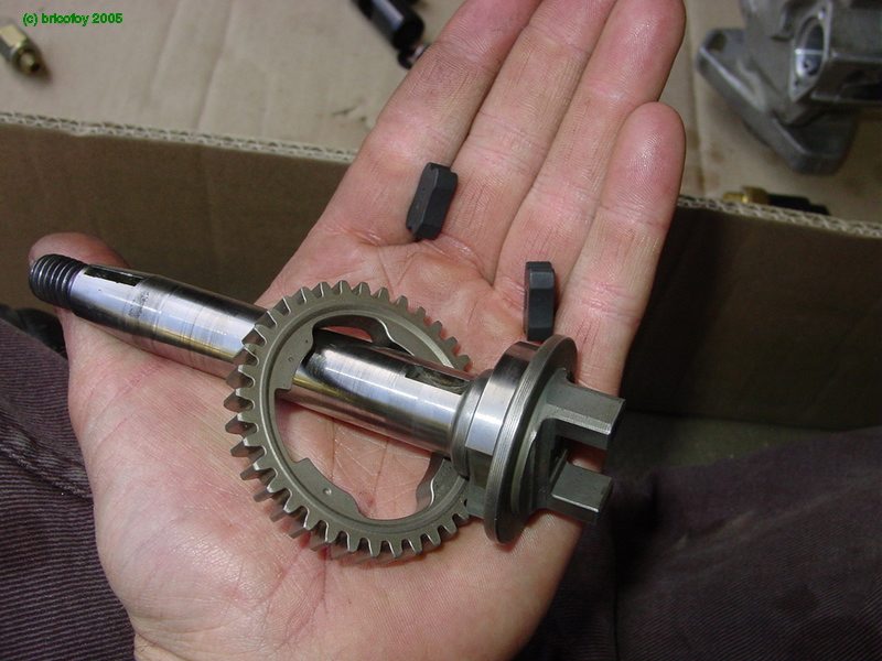
with the governor drive gear.

and two rubber dampers.
then the thrust plate.
and the woodruff key that drives the fuel feed pump.
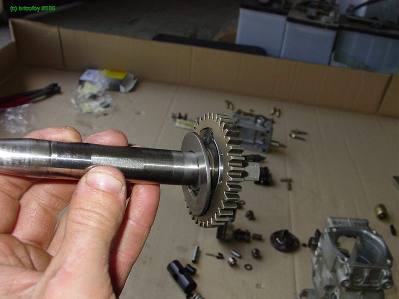
Insert the shaft in the pump housing.
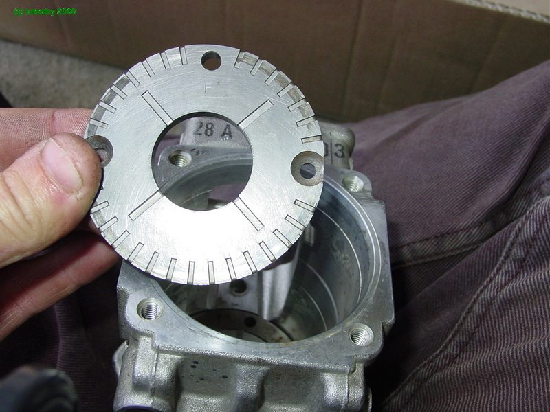
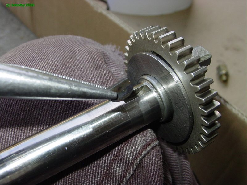
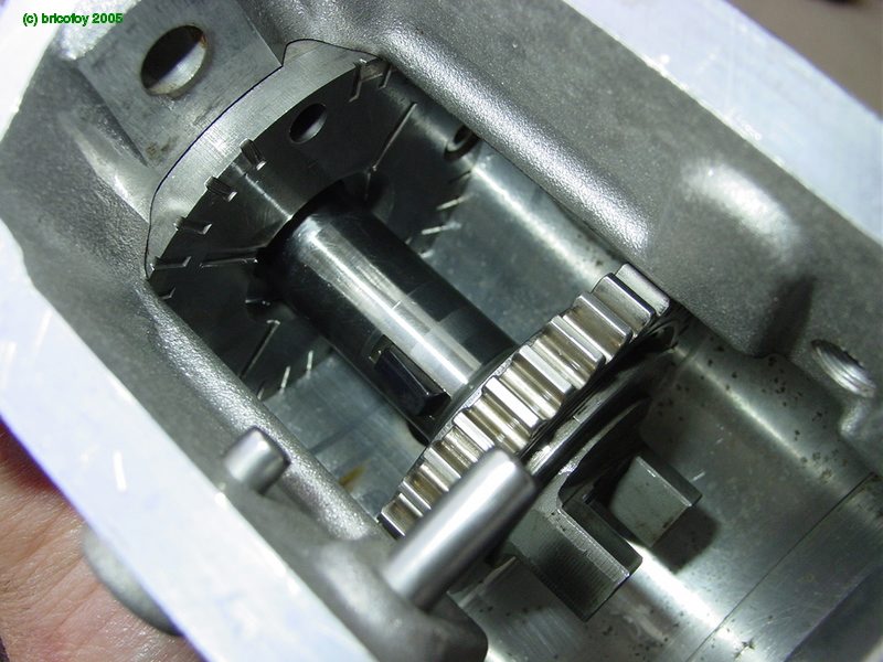
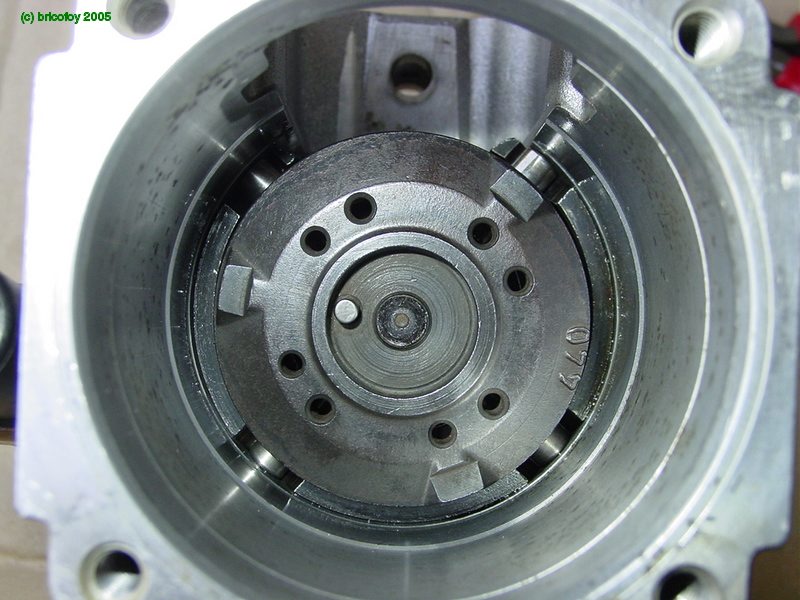
Here is the axial view.

In this radial view, you can see the lozenge shaped hole for the timing control.

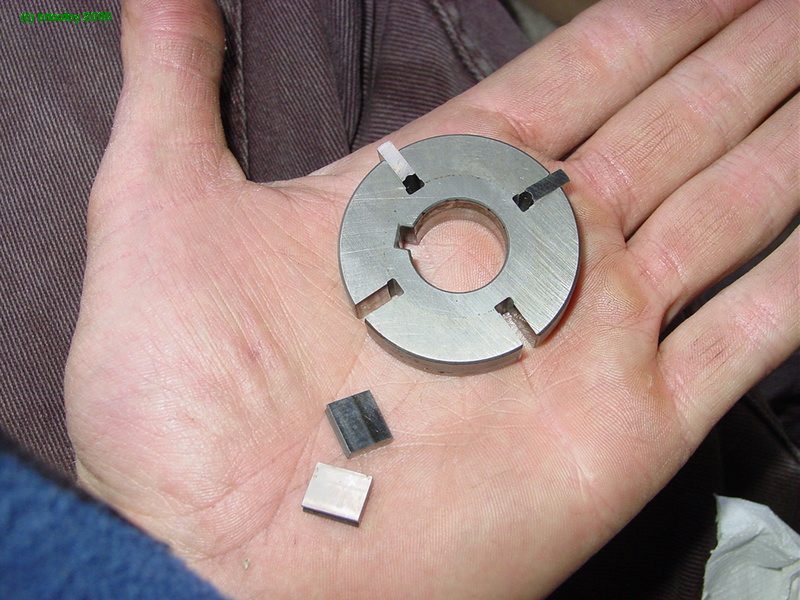
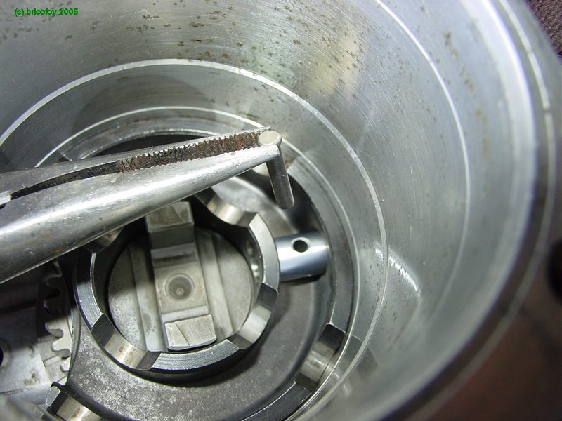
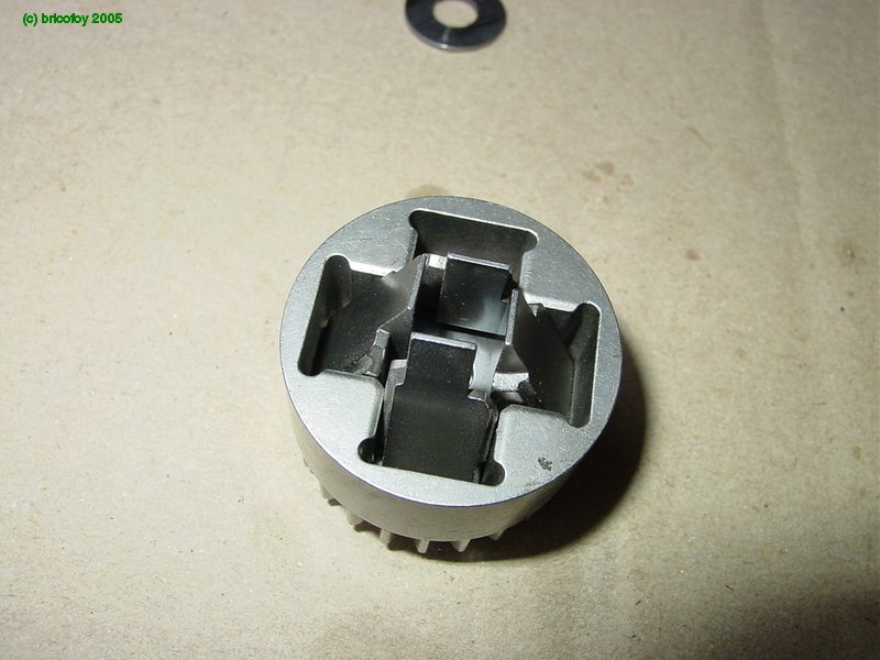
Moving on to the next piece, the roller cage and timing pin.

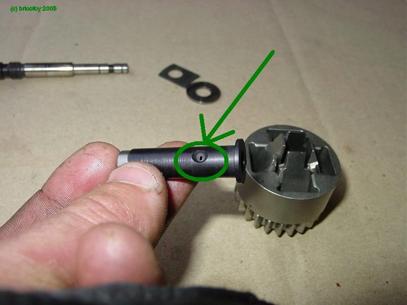
The correct alignment for the timing pin.
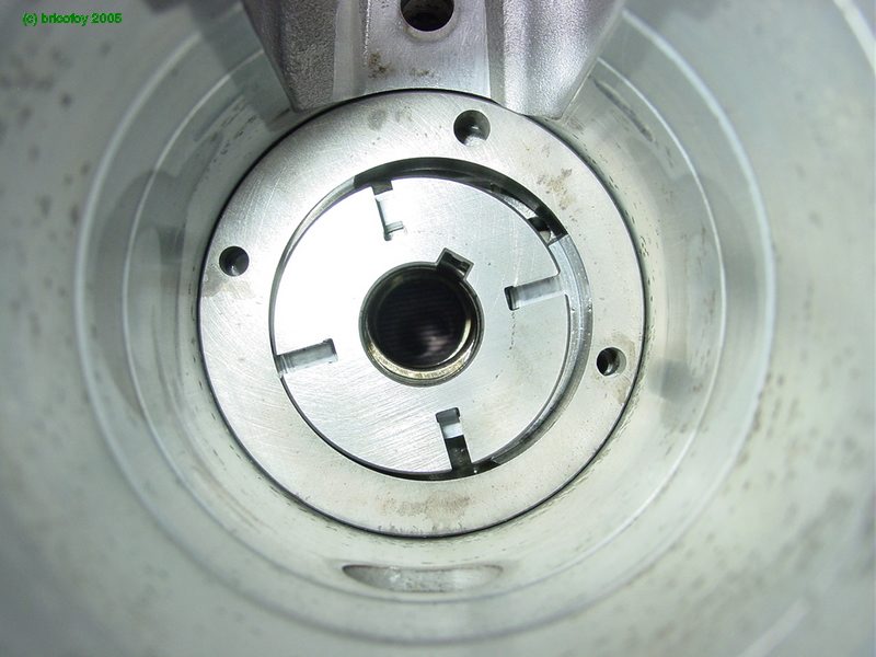
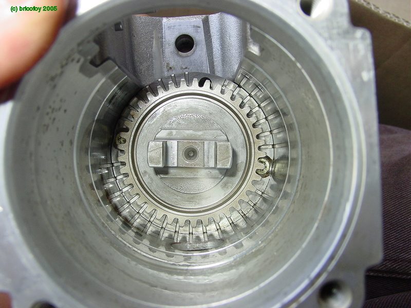
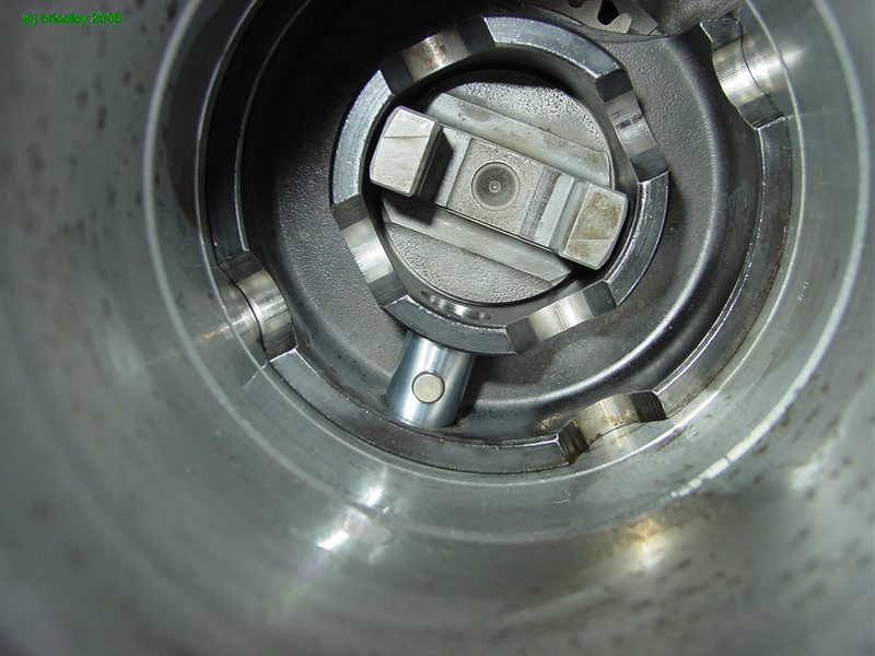
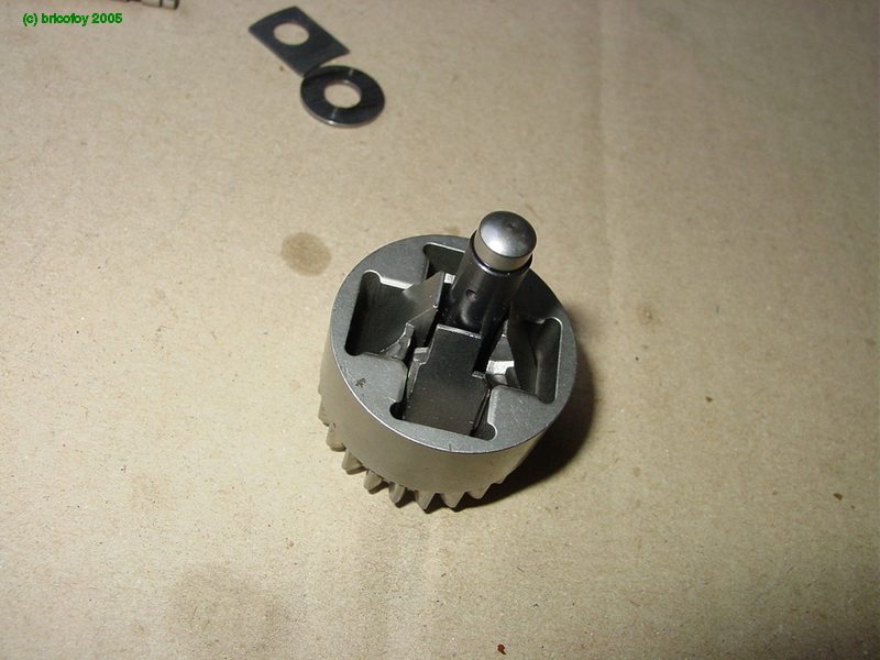
An axial view of the cage positioned in the pump housing.

Seen from the top.

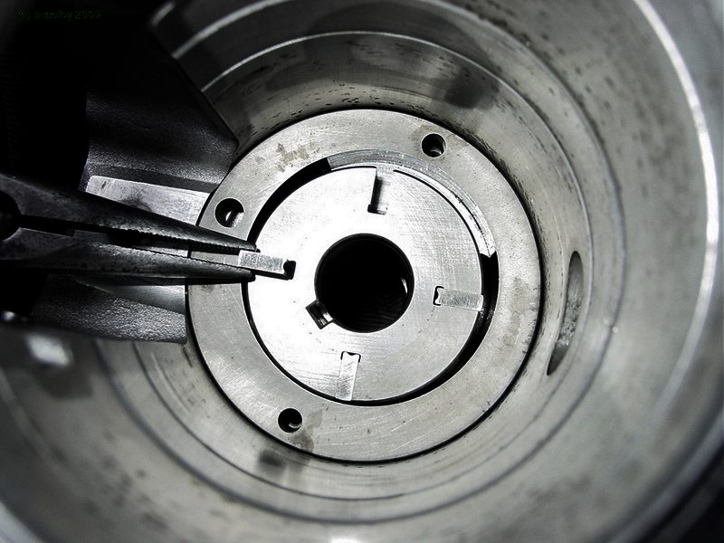
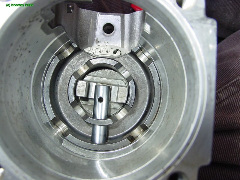
To understand how these systems interact, slide the timing pin into the crossover chamber so it protrudes into the timing cylinder. The pin controls the angular advance of the roller cage.

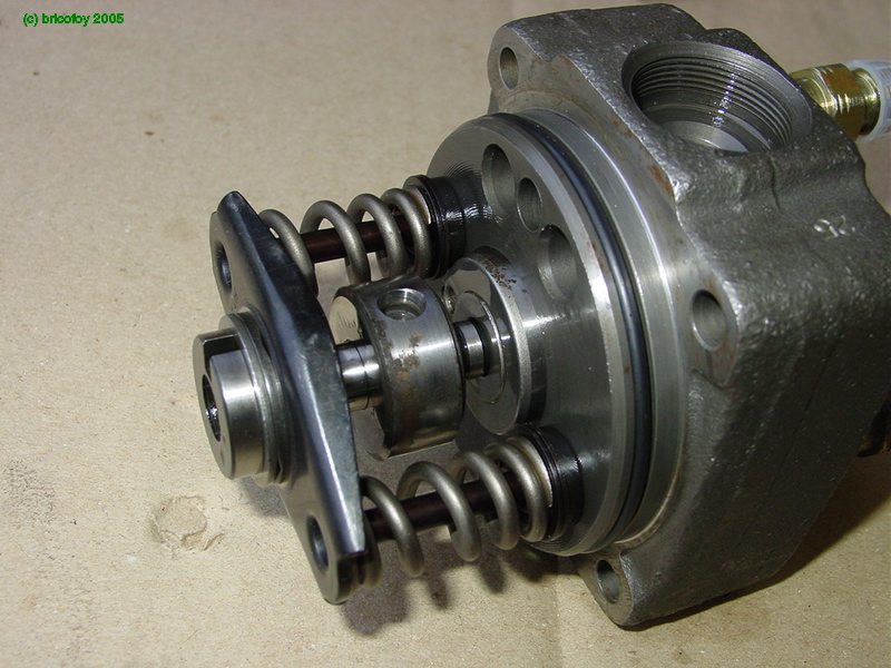
Now slide the actuator back out to install the timing piston.This is the final position of the actuator.

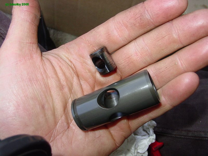
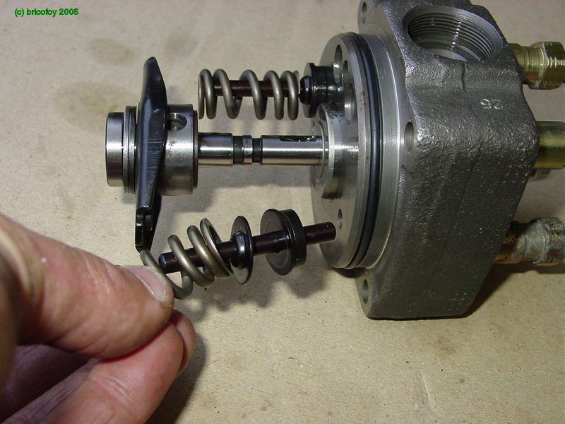
Now we assemble the timing control piston and pivot.
This piston slides back and forth in the cylinder, causing the timing pin to pivot the roller cage into advanced position.

The piston is subject to two forces during normal running. On the spring side, fuel pump inlet pressure pushes it and the chamber side, the fuel pressure inside the pump housing pushes it the other way. The balance of these two pressures set the timing advance. When the inside ousing pressure is high, the timing is at maximum advance.The open end of the piston will clear the fuel pump inlet gallery.
Insert the piston in the cylinder.

Now push the pin down the lozenge hole.
and lock with the pin.
Clip the pin with the retainer.


Cover the cylinder with the new seal.

With the cover screwed on.

Then on the other side, the timer spring and coldstart advance.
There are no controls for electrical coldstart on this car, so I put the usual cover on the cylinder.

Insert the cross coupling that drives the rest of the pump.
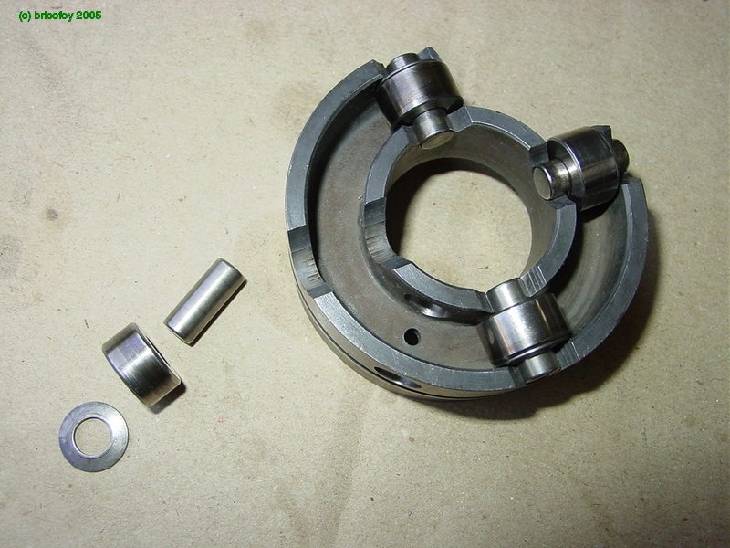
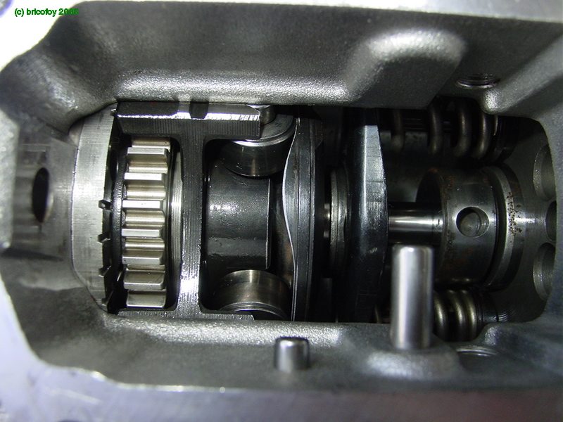
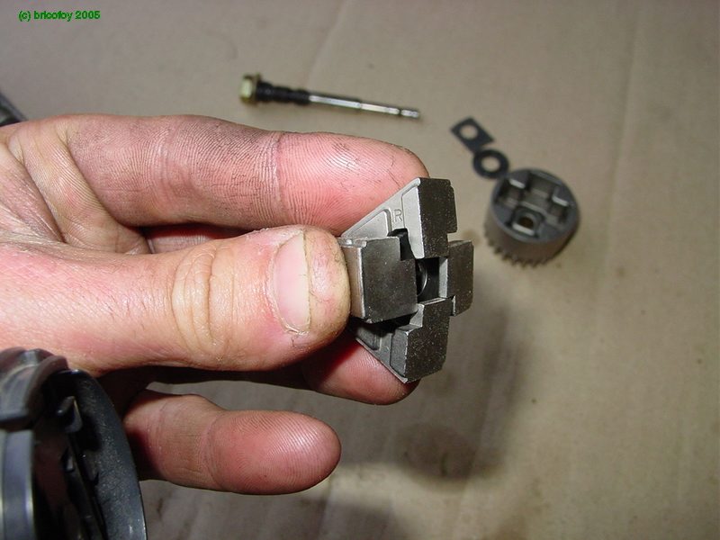
Then the rollers. They are shown here in their cage outside the pump.Note the orientation of the washers, which are shaped to the inside curvature of the outer flange.


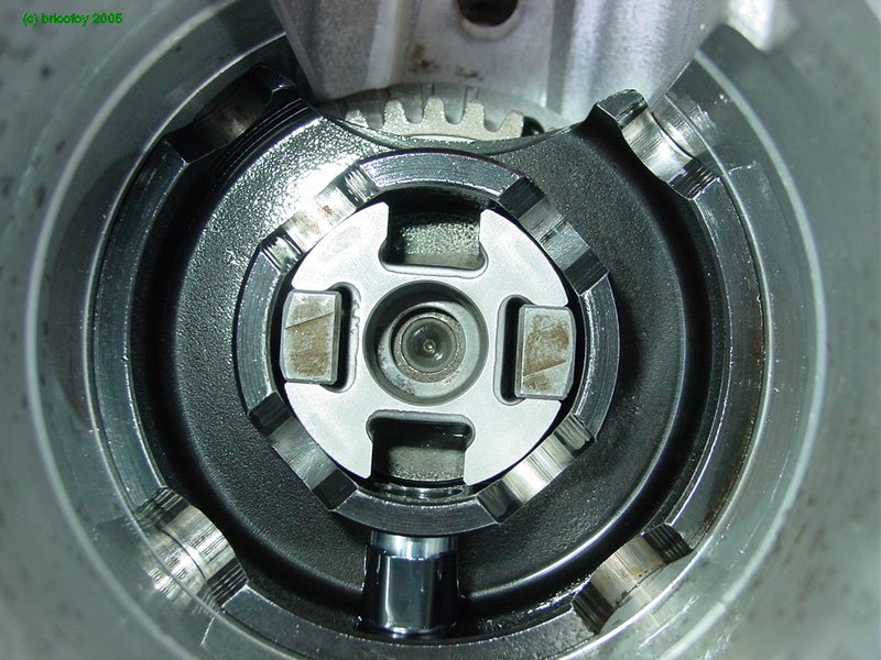
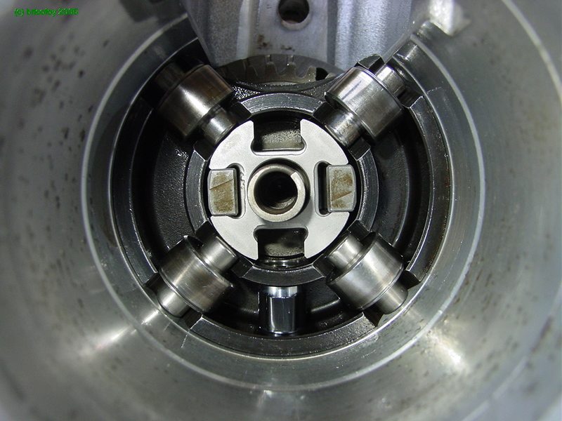
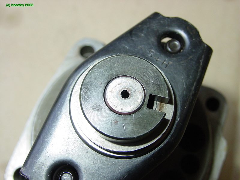
Axial view of the rollers installed.

Insert the spring in the center.
The spring in position.

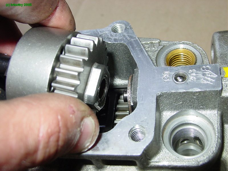
Put the cam disk in, completing the roller cage. The cam plate should fit to the alignment you marked when disassembling. This marking is critical lest you install the camplate 180° off, in which case your engine will not run, or may barely run and die after burning accumulated cylinder fuel.Timing is adjusted by the slight rotation of the roller cage relative to the camplate.
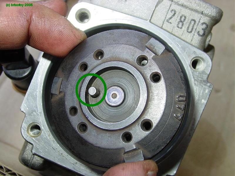
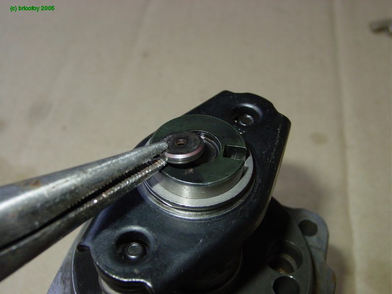
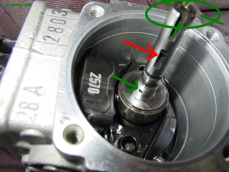
Note the plunger drive pin (circled) mentioned in step #5. On reassembly, the pin should align with the woodruff key slot in the drive end end of the drive shaft. Some models will have a drive gear in place, so to avoid the trouble of removing it to discover the position of the keyway, try to make note of its position on disassembly. To be clear, you should know the position of this locator pin in relation to the position of the drive-shaft coming out of the other end of the pump. See photo #100 which shows the Woodruff slot
The cam lobes rolling on the cage cause the plunger to reciprocate and rotate simultaneously, building the high pressure for injection.

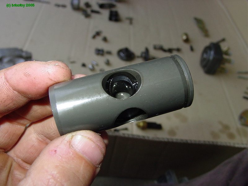
Moving now to the distributor plunger, the piston of the high pressure pump.The spill port (circled) regulates the volume of injected fuel. When the port is open, pressure drops and injecting stops.

The control collar (below), driven by the governor, adjusts the timing of the spill port.When injecting, the plunger is pushed by the cam. Depending on the position of the governor, the spill port is opened by the plunger stroke. That is the control mechanism of the fuel injection.
Insert the distributor plunger in the distributor head.
Then the return springs.
The spacer of the plunger end.
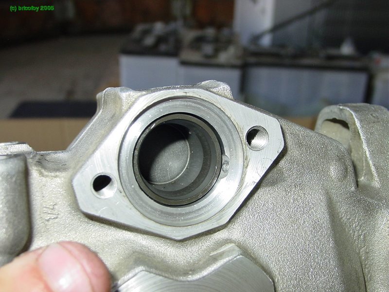
Insert the entire distributor head assembly into the pump, but don't tighten it down just yet.

The radial view.

We will now go the governor tension lever and support springs.

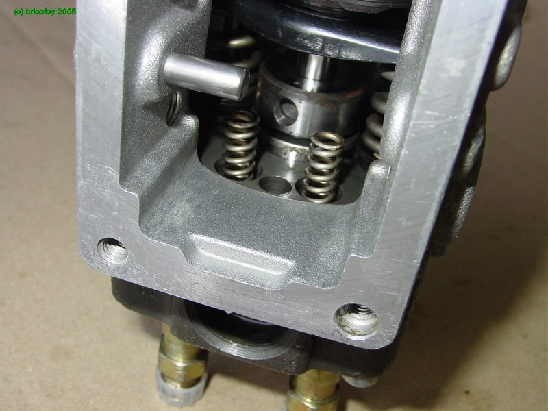
Support springs go in these holes. This part can be a bit of a challenge getting the springs positioned.
The tension lever pivots on three sided bolt-hinges. I modified an old 13mm socket to fit the triangular bolts.
Insertion of these bolts with new aluminum washers.
Now we are installing the lever assembly from the top.
To do this, remove the distributor head (which you did not bolt down) and position the lever assembly so it looks like this.Notice on the plunger shaft the spill port (green), the distributing slit (red), and four intake slits (green) extending into the high pressure chamber. The plunger is galleried to facilitate all this.
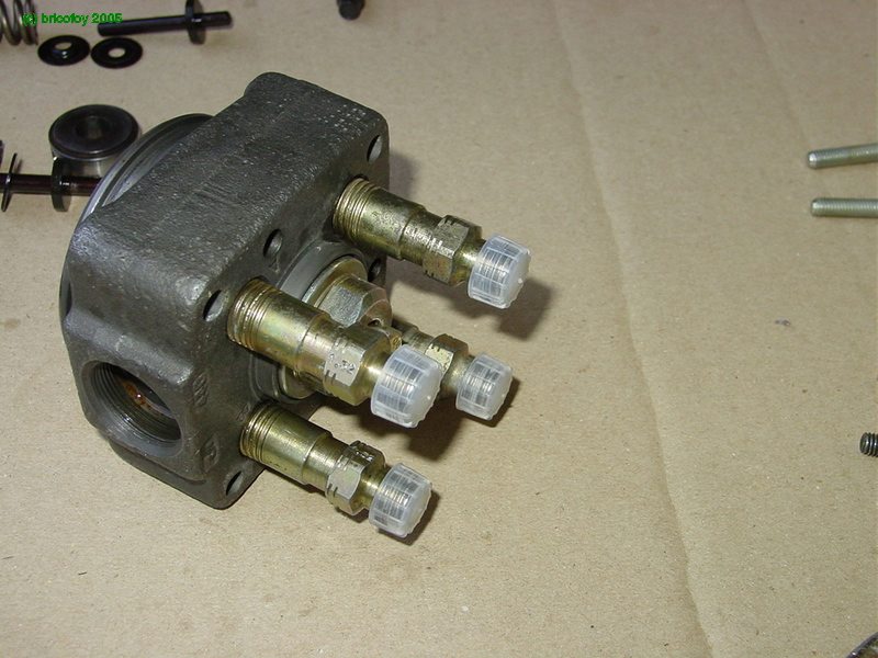
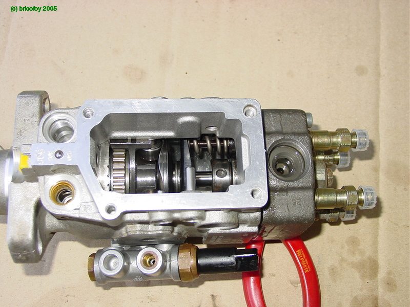
The hydraulic manifold ready to assemble with the return springs.

Now we are ready to install the head assembly and screw it in. This may be a bit of a challenge since the springs tend to fall out, so have some patience here.
The top view.
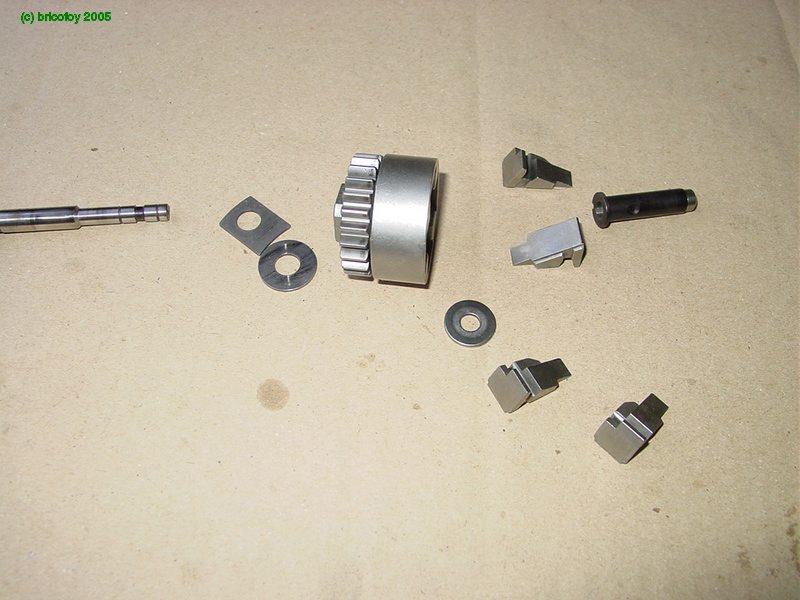
Turning now to the centrifugal governor, here are all the parts.
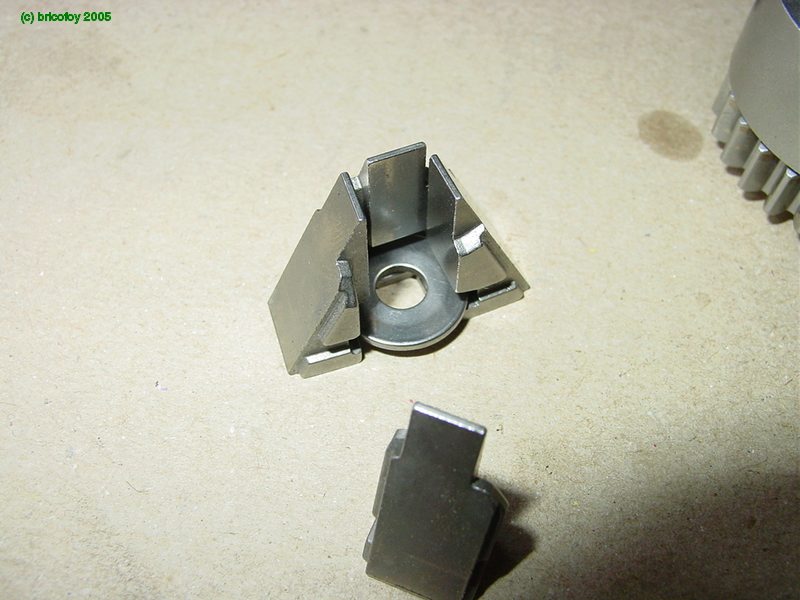
Assemble the flyweights.
Put that assembly into the rotor.
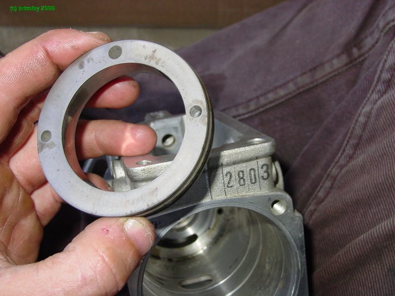
Replace the governor sleeve. Note the calibration hole that modulates initial injection according to load.
Insert the shaft through the rotor.

The governor adjustment screw.

Washers between the rotor and housing.

Install the rotor assembly.
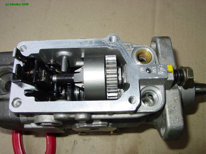
The adjustment of this shaft is important, because it modulates initial injection according to load (along with vacuum, if so equipped). This is why it is a good idea to mark its position at disassembly.
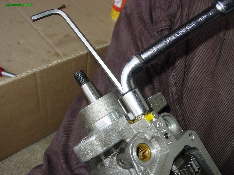
Use a hex key to screw in the shaft to the same position it was before disassembly. Use two wrenches at the same to tighten the time jam nut so the shaft is locked.Now the pump housing is complete, only needing the pump cover and the fuel pressure regulation valve.
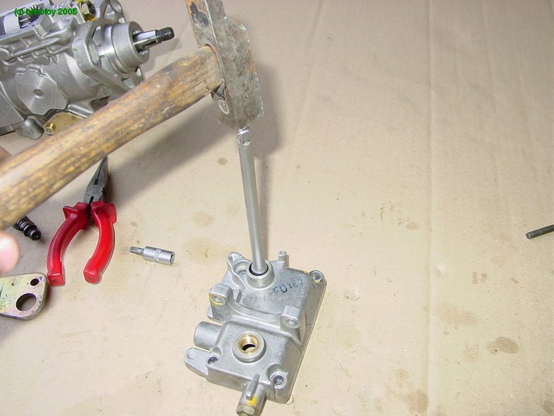
On the cover, drive out the old control shaft bushing.
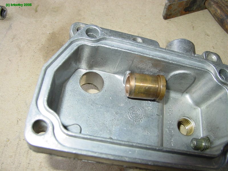

Insert the new bushing from the inside.

Use an old bolt and large washers to clamp the bushing down flush.


Put in the control shaft and yoke.The yoke assembly holds three springs, the governor spring, the partial-load spring and the idle damper spring.
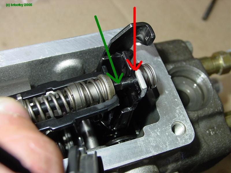
Close up of the governor linkage. Retract the rod so the flat section in the rod (green) slips into the narrow slot in the lever (red).
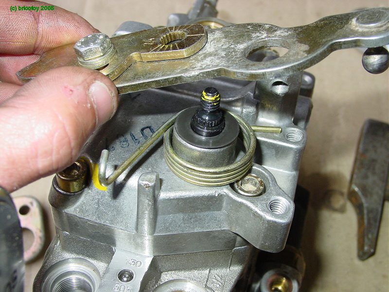
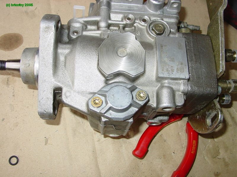
Assemble the speed control lever with its return spring and new seal.
Here you see the idle adjusting screw on the top of the picture, and the maximum speed screw at he bottom.This is one place where you need to identify the lever's setting at disassembly. Adjust it to the same graduation.

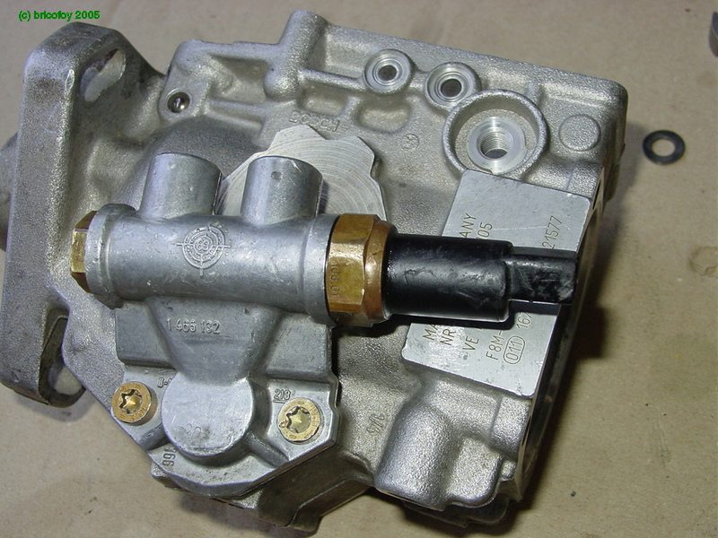
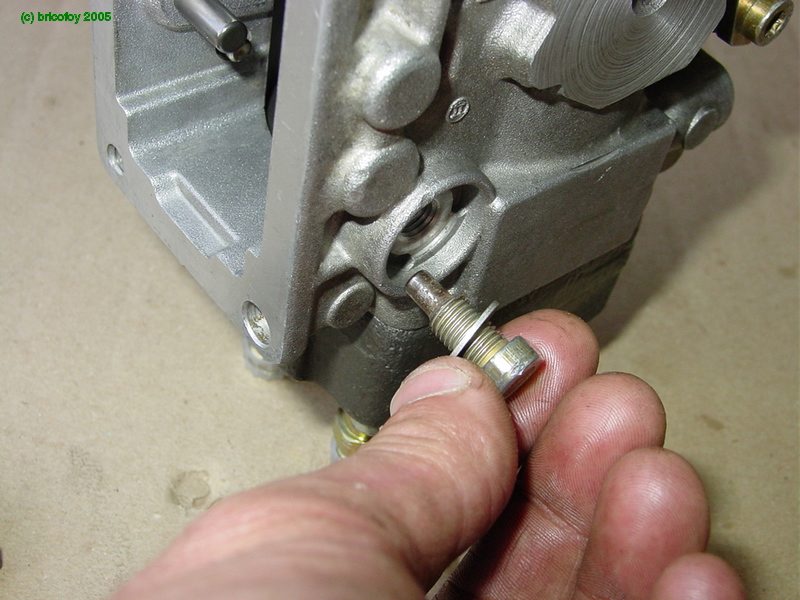
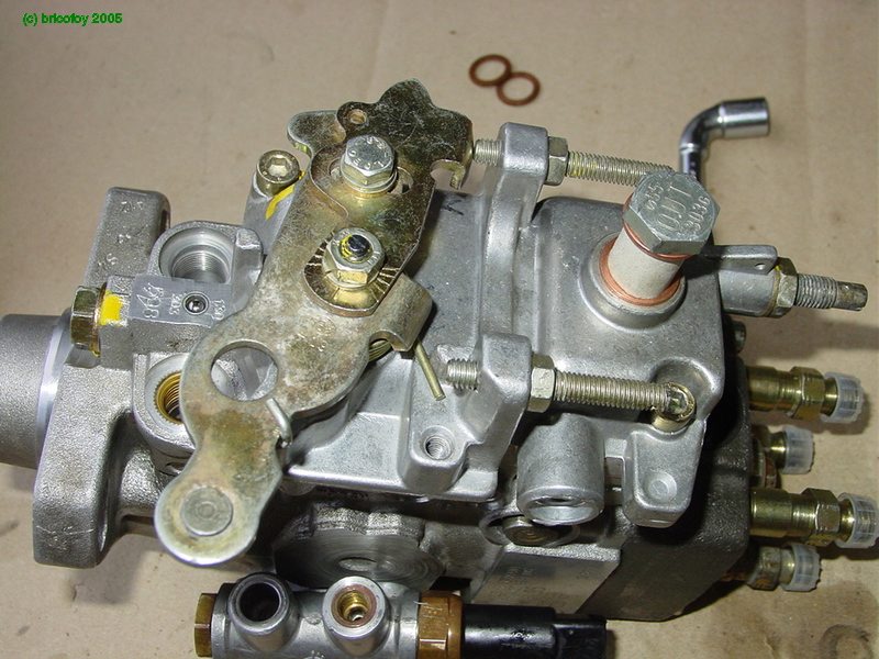
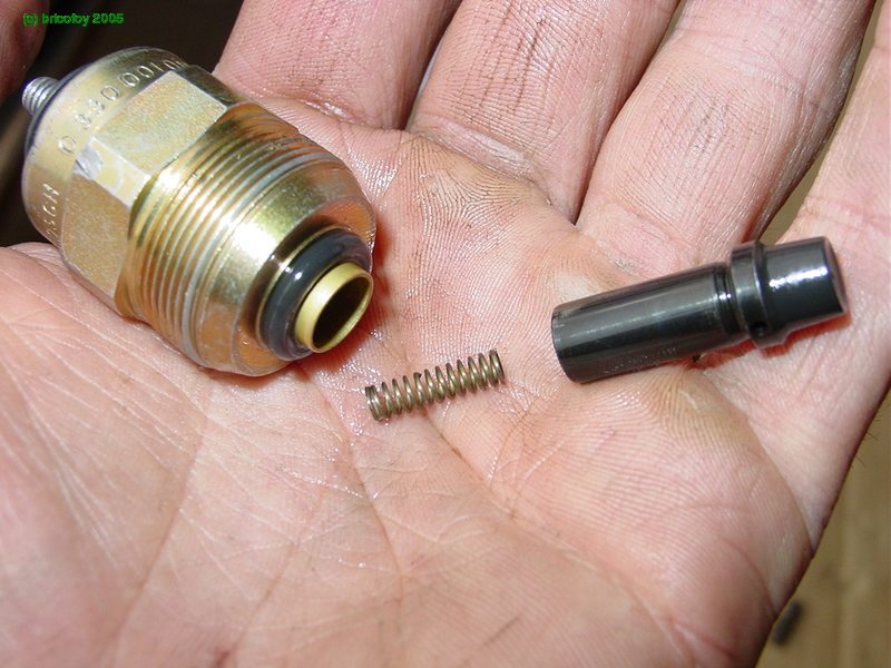
The regulating valve sets the proper fuel pressure for the timing advance and fuel feed for the distributor plunger.Install it now with new seals.
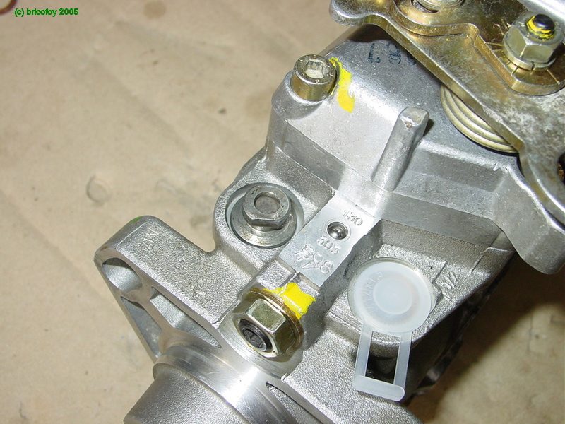
The fuel shutoff solenoid.

Notice that immediately above the solenoid is the full load adjusting screw. You may prefer to mark the setting of this screw before disassembly.

Last piece, the driveshaft seal.
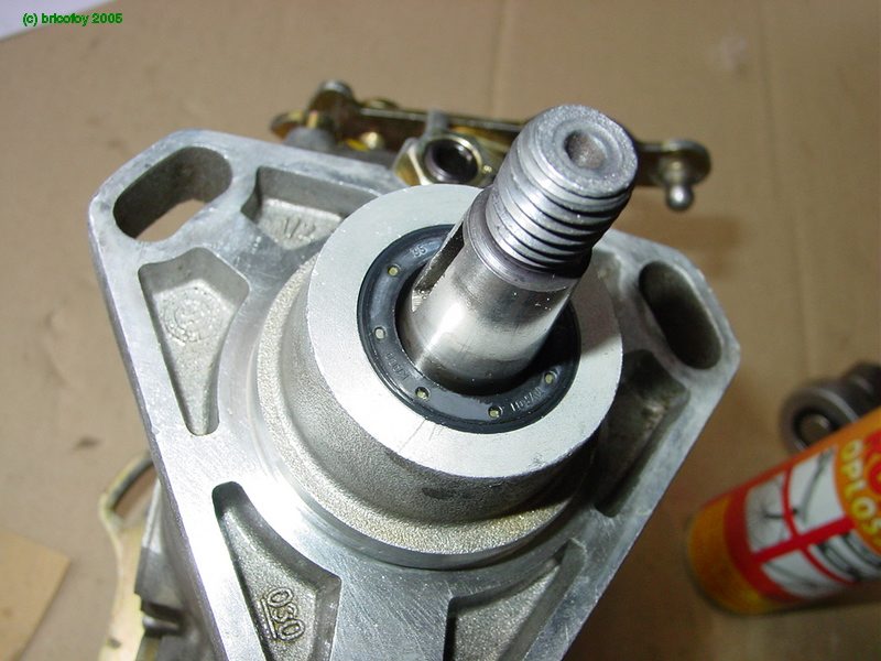
The Woodruff slot in the input shaft.

You have done it! Not as hard as you thought it would be.All that is needed now is to mount the pump!